Another pause would certainly be in order if you’re still reading along, or if you are curious to continue you can probably pass this next gallery. We just have a lot more engine internal parts, bearings, gaskets, seals, springs and more. I will note the most intricate piece here being a new self generating, 12V electric dual power stator and adjustable CDI ignition system. Very, very trick little kit here that matches up perfectly with an oem wiring harness, so we must have one of those to right? This conversion comes from the UK and Rex’s Speed Shop, along with many other such devices for other bikes, and other kits and electrical pieces for the XT500.
Next, if anyone ever had a reason to fraud a motorcycle vin, let alone one that now needs leading zeros just to work with the dmv computer system, and is over 40 years old, well here is your invitation. I couldn’t postulate a reason why this would need to be done, and this entire process would undoubtedly prove whose vin belongs here. Beyond all of that, the need to note this stamped vin and vin decal with such detail was in fulfillment to meet requirements to have a new decal made. While the vin stamp will still exist after powder coating, the decal obviously won’t, unless it was desired to keep the original, which would not occur, if that’s any sunrise. Searching led me to find a Canadian based business, BDesigns, who will accurately match such decals or stamped plates to meet your specifications. They require various forms of identification to prove your identity, ownership, and information pertaining to your reproduction needs. All of that said, any organized individual should easily be able to follow all of this, and receive a great quality reproduction at a fair price no less. (I do suppose that my agreeableness on such things throughout the process would be laughed at by others, but I’ll spread my well-earned money to areas that seem right to me, of which all in the process truly are. Though I’ll admit I could have been a little less agreeable with long timeliness, but as stated before all good things in time).


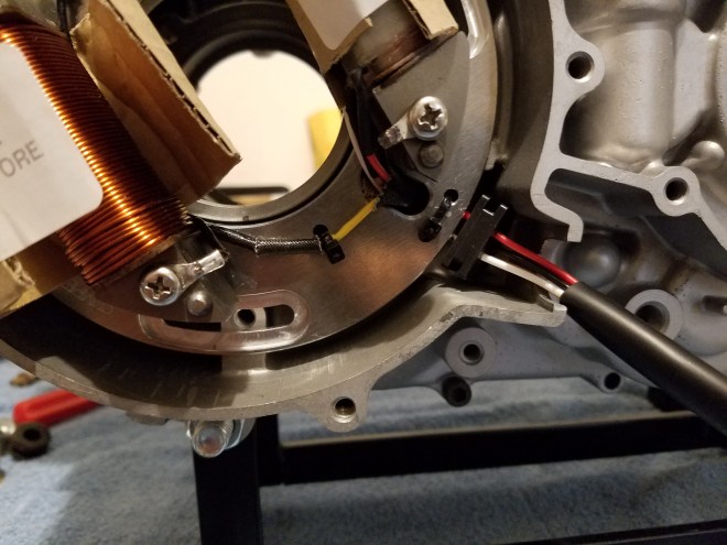
One problem that did arise with the stator system is shown here. As you can see the grommet was misplaced in manufacturing, which Rex’s acknowledged can occur as their parts are all hand finished. This would be an easy enough fix, though tedious as to not damage the wires to any degree.
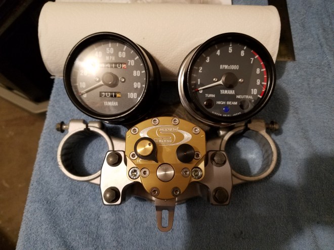
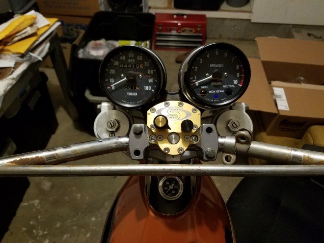
Another sole picture to follow, here just looking at the gauge cluster being mocked up with the upper tree and steering damper. Even with the difference in visual depths between each instrument, it all fits together rather well, not too much going on, but everything right there in a small visual spectrum.
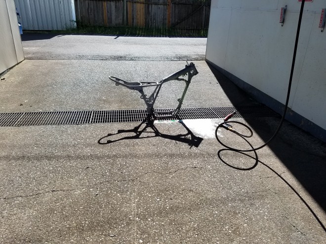
More parts from the blasters, or rather one intricate part, and a different blast media. There was already welding that we desired to do, this enabled a clean base to start from, and observe the condition of the frame as a whole. Thankfully, the only area that would need attention from the passage of time would be one footpeg mounting spline. There was some minor pitting near the terminals from the battery, which is to be expected, but was deemed no issue.


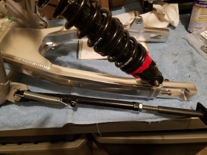
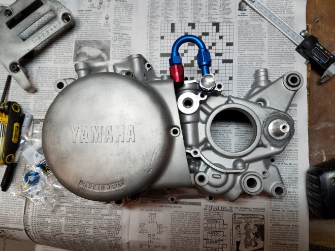
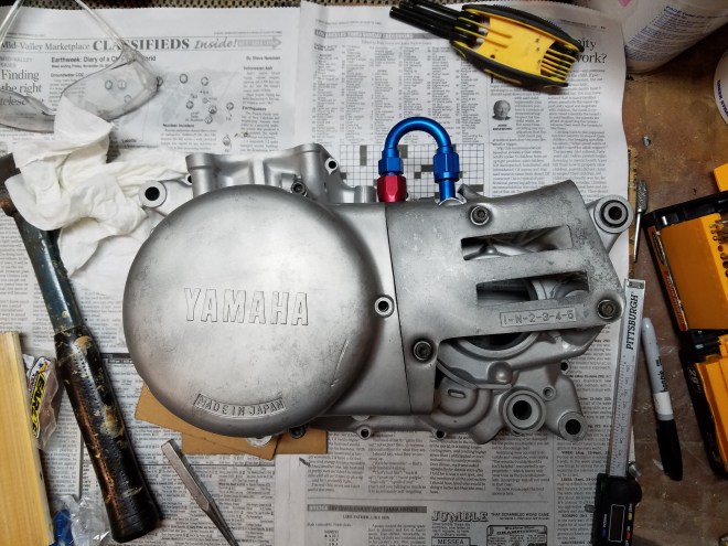
More random projects and small purchases will litter our efforts for a few more weeks before the start of another fire season, during which work will still be occurring thankfully, just not by me directly. So, small parts and the checking of clearance between the swingarm and kickstand base, trying as best we can to keep lustrous parts as they are for now, if they get marked up during riding then that is definitely acceptable. Another technical tip, the earlier oil pump pressure side face uses 3 mounting bolts, vs the later 5 bolt faces. With our new oil pressure pump we can utilize this fact for better sealing power, aiding in both pressure and negating oil aeration.
A plethora of pieces pertaining to oil delivery here, with an abundance of AN fittings and stainless braided line. While many of these hose ends won’t be used, at least having them on hand allows many different options where needed. Again, is all this excessive, yes, but actually only one original oil line could have been used anyway after the oil cooler addition, so we will make everything match and enjoy doing so. Further, our first image may be unknown, but that will be our new air/oil separator. I’ve never been the biggest fan of routing crankcase pressures to atmosphere, probably only in hopes of keeping things clean regarding the machine. Plus, a fraction of a horse power is to be gained in theory if routing back into the intake to control crankcase pressure against combustion chamber vacuum.


The application of a few of the aforementioned oil parts. Not knowing exactly, the oil gauge will just act as reassurance that the scavenge side of the oil circuit is working as expected, volume flow over pressure here, I’ve found anywhere between 3-8psi to be within tolerance. The necessity of various oil adapters is apparent here, although these could have worked, the intention was to have unobstructed oil lines where possible.


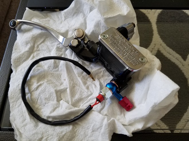
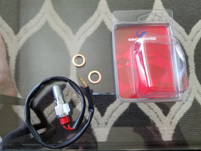
Its been awhile since we’ve last seen this piece, and is essentially complete at this point, though still awaiting its brake fluid line construction. With the addition of a front disc, a different pressure sensor was required than an electrical open/close switch, and just such a device exists to serve a similar purpose, though working of fluid pressure instead. For those who hate AN anodized blue and red combinations, you won’t find comfort in the overall product as there will undoubtedly be many, but this was my first project where they could be used, and they definitely will be used if one couldn’t have deduced that already.
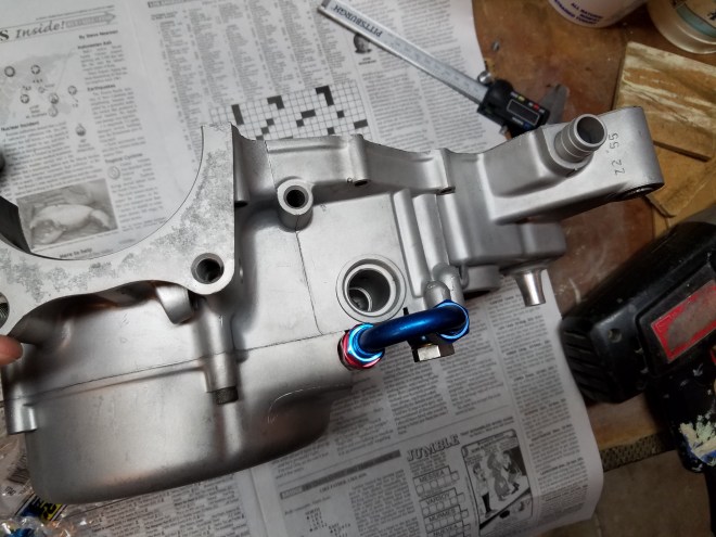
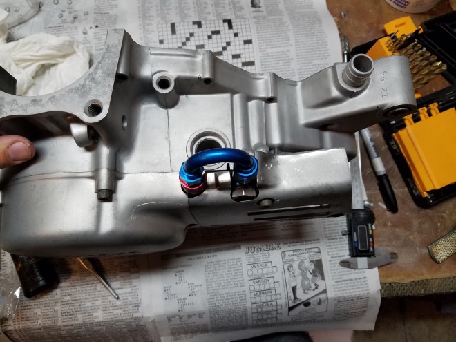
Yet even more AN fittings, which at this point might serve as a great source for another project in the future. One style that I hadn’t seen on any other builds was to bring the return line from the frame into the crankcase while taking the same path as the original line, but with added modification. The choice was to come out of the sprocket cover and return right back, all tucked neatly behind said cover.


Now a visualization of where the oil cooler is to reside. Again, any complete system just really didn’t look correct to me, so some fabrication would need to occur to make it all work. The tape is for temporary security as nothing is attached at this moment. You can see the idea of how to route the inlet and outlet lines here as well.


Small randoms, oil line holders to keep things tidy and new electrical lines for the gauge illumination. The original gauge cluster harnesses were actually in fair shape, one benefit to these is that they contain a 194 wedge base bulb which has more LED availability, versus the stock twist base style.


In order to attach some of the oil lines there will be necessary work to make the adjoining banjo bolts compatible. I actually have quite the affinity to taping new threads, though not as much in the boring that occurs beforehand. The reason for this is simply that it all occurs by hand, I don’t have my own drill press, though that’s not a great excuse as many are cheaply available. Like many things though, so long as proper care is taken in the process and the results are sound, either is acceptable.


Another explosion of purchases, here mostly from Vintage Spoke, and the last more from Partzilla. The most important parts here, though they are all individually important, would be replacement black side covers and a new handle switch. Previously I had bought decals in hopes to restore the original unit, but further inspection would observe most terminals and electrical contacts to have eroded to dust. Many times along the years I would have small concerns or needs with my Vintage Spoke orders, and they were courteous and willing to help. A very touching gesture with a simple thank you letter to me came here, thus requiring my acknowledgment and sharing. Thus, I provide my dear thanks as well, hoping that all of this, the project and story brings joy back to all of you.
As giddy as one can become in receiving all of these wonderful things, there is much work yet to be done, so dredging on with fabrication once more. First, some time has passed since blasting the frame and rust has once again returned before welding has had time to occur. This will be my first use of naval jelly, which did exactly as intended and kept further rust from occurring for almost 2 months before it all became cloaked in powdercoat. Here we will also deal with the worn and pitted footpeg spline, and make the stabilizer mount more suited to fit the frame. On the spline, there is actually great ease in the simplicity to fix, first you will need part 3H0-27212-00-00, which is a brake pedal shaft for the SR500. Next, cut the existing spline off of the frame, and the new spline off the pedal shaft. Now, you could weld it on as is, but you can do better yet and drill the inside of the new shaft, tap it, and quite literally screw it in place with a bolt that has long enough threads. This way, it is centered correctly and has a threaded bore just like stock, where a bolt can be used to secure the footpeg, much like the TT500 functions. My apologies for not getting any such pictures of what I just described, we all make mistakes I suppose.


Yet more fabrication, there will be an end eventually. In truth, breaking this apart over so long allows for a few small tasks to be finished with thorough thought and care, rather than rushed haste, but that is also a luxury of having no strict deadline to meet. Next, work is needed on the upper tree for clearance with the stabilizer mount, steering lock extenders to be made and welded so our forks don’t destroy our tank, and mounting of the gauge cluster base. With the rake of this bike, there will be issues in moving the bike around with ease say in the garage, but there is still roughly 60 degrees of lock available, down from 90, but being a street only machine I don’t require as much maneuverability for slow speeds as trail riders do. A thanks to Brad for welding this all up, and our failed attempts to weld the oil cooler together, which turned out to be a very good thing to be seen later.
I hope here you can admire the oozing of character, construction, and overall pure coolness. Unquestionably there are others who feel the same, or I hope that this is the case. At this point the fabrication for the front end is essentially done, for the large mechanical functions at least. Note the dipstick oil temp gauge, white or black being the choice, and is another vital piece of dynamic information that falls into visual perception quite well.
Just some finesse to apply on our welding work. Some grinding to make it all look more finished, as well as exacting filing to get the steering stops just close enough for the forks to not hit the tank. Although, it’s not the forks necessarily, but the headlight mounts that are the interference issue. The bolt receiver protrusions required a fair amount of grinding to work, in a guess and test fashion if that sounds correct. Another area where only keen eyes, or reader, would ever know about this little raw feature.
Another needless picture, here we have the frame being cleaned, for which main purpose I can’t exactly recall, but likely a thorough cleaning of the oil tank.
Having now come back from the first leave of work for the summer, having traveled to the Southwest for a few weeks we have a much anticipated delivery of one crucially important and fundamental piece, as well as a few others. The fundamental aspect here being the crankshaft, whose return visually shows the adventures of its own travels. The Carrillo rod now has a resting place with a purpose, the resting place itself having seen machining to alter the crank pin location, mass reduction, and some clearancing on the rod webbing which is yet another issue to be dealt with. On the masses themselves, I have included a detailed description of what occurred for those who would be curious enough, but broadly it is lighter overall and thus allows to achieve power band range somewhat sooner than before. Otherwise, there is a billet gas cap, the only such one I could find for the female threaded early tanks and are made is small batches, so I’d advise order ahead if you feel the need to acquire. There are obviously a few oddities included that were on long back order times, but were available nonetheless.


More travels for work, passage of time, and completion of a much needed task. On a side note, this was actually my first time being home in all 7 years of firefighting on the actual day of my birthday. Now, personally I’m not one to yet celebrate holidays as there is a certain dilution that brings to the other days of the year in my eyes, instead caring and seeing the charm in each one. Also, shot out and thank you to the boys who came over as well. For the first and only time during the process they saw what I had been working on, followed by needed enjoyment out on the town, even if the town is small enough to run into old coaches during outings, refreshing indeed. The powdercoating itself looks amazing. Black with a high percentage of gloss, 80% if correct, but not a mirror like finish, there will be plenty of polished objects to fill such a void.
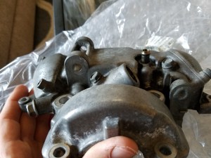
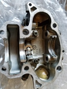
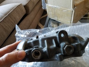
Another useful technical feature worth mentioning here. How engineers end up making design choices and changes is actually very intriguing to me, here hinted a slight variation to the rocker cover from different engine models. All XT500 motors had the same rocker cover apparently, the SR500 I cannot say for sure, but the SR400 ended up attaining and upgraded version of this piece. Simply, there is more webbing/material in the top of the casting, as well as through bolts to hold the rocker shafts in place. Fouling of the cover in the rocker shaft receivers can occur without this slight variation, and requires machining and bushing inserts to fix. Instead of ever having to do so, hopefully ebay will suffice our need, though this is a pretty illusive piece to find.
Two unrelated pieces here, first a new endless cam chain, 219FTSS x106 which should be stronger than stock and handle the stiffer valve springs accordingly. Second, the finished vin decal ready to be applied. Yet another aspect that adds character in the right ways, and if not, it at least emulates a stock one which has its own appeal.


Here, we next have an eclectic assortment of tinkering that needs to be done. Only for the sake of depiction, some pictures of the seat foam and pan conditions and will be dealt with shortly, a very rewarding process with the results that were accomplished. Some grinding and sanding of powdercoated pieces to ensure easier fitment during assembly as masking doesn’t always get everything. Clearancing of crankcase webbing to allow for a connecting rod interference, which as can be observed, was actually a fair amount of material, this after the rod had been machined down some .100”. Lastly, the efforts of our aluminum welding, which gave enough actual metal connectivity to feel comfortable to fill with putty to finish.


More explosions of newness yet again. A new tool, a few new parts, and the results of a friends efforts. First, in desperation to accurately torque fasteners with absolute confidence, a digital torque wrench is now upon us, and to the shelf goes an old but well used tool. Else, new parts include Protaper bars along with some adjoining pieces, an appropriately sized and finished engine guard, new rear fender to replace our damaged one, clutch assembly, and a full LED headlight and bucket to suit. Lastly, the tank has had all bodywork performed and properly primered ready for paint. I’ll confess some curiosity to try bodywork at least once, but here I was still working and just needed it to be done, with a focus on detail far better than I could provide no less.
Recall the brief mention to our inability to weld the oil cooler effectively? Here is the solution, or at least the first version. Instead of welding the brackets directly to the cooler, it was possible to use an available mounting bracket and attach to that with simple fasteners, a better and modular solution should anything ever happen to our cooler. Else, new billet indicators that have just enough detail without being egregious, a thorough polishing of the engine guard and examination of yet more blasted parts, the last of such efforts.


A gallery here of my idea of how to bring the oil feed line from the frame into the engine. There are sprocket covers available that would already have an opening allowing the same routing, but I didn’t see another example like this, actual creativity on my part I hope.
Onto more fabrication for the next few galleries, all of which deal with an amount of metal fabrication and assembly visualization. We’ll start with mating the front fender to the lower tree. What was an issue was that from front to back the fender has too small of a mounting area to make use of any possible threaded area in the tree. The solution was to make a middle plate that attached to existing threads in the tree, and allows for mounting through all fender mounts as well. The piece itself is somewhat rough in that it’s not perfectly symmetrical, but it works as it should. Some more polishing on various pieces as well.
A liberal application of long lasting metal techniques are on display next. Sparks bombard a tattered piece of canvas as a result of the process, only to be followed by more precise filing efforts, both filling a niche of archaic processes. There was a need to make an inner mudguard, well a desire, though this will provide an excellent, sturdy mounting surface for the air/oil separator, all the while looking good in the meantime. There is also a need to have a mounting area for all of the electrical components as the original battery hanger will meet the parts bin, we’ll have no need for a battery in time. The fabrication itself was actually quite simple, the only requirement being straight cuts that can arise with a metal guide that a cutoff wheel can follow. All in all, I was very happy with the results as simple as these parts are, even if they’re not completed quite yet.


The results of a long awaited design idea are now a reality. A local individual from Wright Prototype was able to make this piece for me, and nice enough to give extra ones that he first made in error that had the wrong angles. The image that closely shows the spacer on the head gives you an idea about making the carb sit somewhat more straight in the frame. Also, the mounting base will be changed from 6mm to 8mm bolts for added security since there will be no support like that of the original air box.


The results of the piece, and while not perfect in terms of carb alignment this should serve well, note the minor trimming on the plunger arm to add just a few more degrees of rotation as well.
Another milestone that sparks temptations to what the result of this entire process might soon become. With the sparse addition of more metal, the idea begins to take form, a form that is at this point everything I could have wanted, though I am inebriated on completing.


Continue below,


