FURTHER DISASSEMBLY & ENGINE FOCUS
Back to reality we now travel just for more observation. What we have going on is thoughts about how to deal with our USD forks interfering with our tank and steering geometries. In truth my mind didn’t know exactly where to go, cut the tank and make concave inserts, reduce the lock to lock degree, move the tank back or choose differently? We shall decide later, plus, enjoy the use of paracord to secure the front fender, a must have for all wild land firefighters.
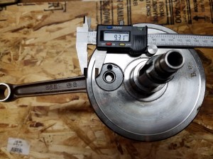
Closeup of the front brake assembly here, even an uncaring eye would claim this is more appealing than the original disk if you can remember what that looked like. Also, needed measurements for the steering stem machining and spacer creation.
An oddity, our first tool that will be created, why I cannot recall as such tools exist and would match my addition of acquiring new tools along the way. Even the gentleman at the store would politely ask, “why sir would you need such items,” as I would explain as a race installer and collective ground was found, he had an exact understanding of what another brought before him.

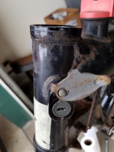
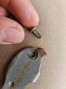
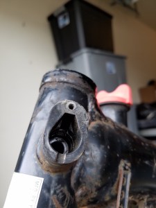
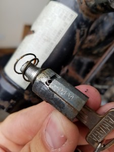
Onto the steering lock assembly and races. The lock is simply held in place against the interference of the lock cover, which can easily be hammered out rather carefully. Along with this, you will note the key code on the lock, which will be similar for all locks on these machines, ignition, tool box, and side covers, where replacements can be found if looking hard enough, though you might at this point be limited only to specific keys.
More pictures again (could you believe it), this time just more ideas for what would have to be done to fit the front end. I will find that my headlight mounts would also hinder here, useful information.
From here our focus begins to first from outside macro design, to inside micro design. There will be one further gallery for the rolling frame design ideas, but the focus shifts to our hopes in the motor and other more mechanical aspects. At this point I was fully engulfed with that previous idea of excess, I did desire a street able machine, but in great excess. Bearing that in mind, more specifics are to follow, possibly some drawn diagrams and notes, and lots of disassembly. Likely because this part was currently separate from the bike, I’ll make the choice in carb, a TM40 flat slide pumper. This may prove to be far up the spectrum in size for effective port velocities on the street, but at the top you can know that its there. I’ll also choose to mate up a separating heat plate from head to carb, only noting likely its aesthetic purpose.


More new parts. What you will note is the arguably poor choice to place items on a glass table and then take their picture. Well, that is a very common theme that will continue up until the present day, so enjoy them as they are or scroll on past if you must. Another small reason to chose the TM40 carb was for its use of a dual cable setup, which is the same as stock, though I will need new such pieces.


On next to the carb on the bike. I could have been satisfied with this orientation, but I wanted to have no interference between the carb head plate and the accessory head fins, which you saw earlier. The hope would be to fit a spacer between the carb boot and head, moving the carb away from the head, though this would further create another interference between the carb and the frame. At the time, I tried a spacer as best I could find to test this idea, though this would only be used for mock up purposes, and I would later design one for CNC work, though it will be some time before we get there.


Not to brag, but I am a large and strong young man. All of the previous work came from unassisted means, all was handled, lifted, and moved by hand. There is a charm in doing so, much like the joy of lifting the frame and engine into the back of my truck, or placing it on heightened wood blocks to do some assembly. Though where possible, I acknowledge the value in finding a little help where needed, here for my back no less.


One feature on the TM40 carb is a cable style choke lever. While there might have been a suitable area to mount such a style, I opted to replace with an on carb pull for overall ease. Otherwise just a few pictures of the top end, for what reasons I am unsure.
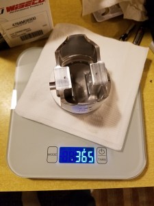
A thwarted ebay experience now, in that an incorrectly labeled and described product would dictate return. This Wiseco piston 4045M08900 is 89mm bore at 10:1, what was ordered was 4764M08900 with same bore at 9:1. For the decision of hopefully a longer living street engine operating on pump gas was the determining factor, and 89mm bore leaving some room for rebore if needed without resleeving past 90mm. Even at 9:1, another factor will later bring this static ratio higher independent from the piston, I’ll leave speculation for that then.


This next stage would come after some weeks of driving around the southwest and exploring, and having had the opportunity so far in life to work across and see much of the states, I can say some of my favorite lands and features reside here, though not currently willing to reside in their presence. So, what is bestowed on us is a heading pile of parts that were ordered along the way. What is contained here does include wallet penetrating engine internals, and the wallet is happy to provide for such needs. Look through as you choose, the special parts mostly coming from Gary Hoos Racing, like that of our stroker connecting rod (YA-TT5>-05571N Carrilo Rod 3.5mm), megacycle cam 251-62, and 2mm over sized intake valve at 49mm, we are beginning to create quite the beast. A quick tangent I’d like to share is that of just how many places this project has had influences from and how incredible a time we live in where the world is so small and connected, and take a moment to appreciate how incredible a time we currently exist in. From recollection, and at the time of writing, parts themselves have come from the following countries, let alone lands within them; United States, Canada, Germany, United Kingdom, Germany, Japan, Thailand, Australia. Even then I believe to be omitting sources, even after looking over the build purchase list broken apart from each year and part provider. Just simply appreciate this fact of our modern world, and note that while you can’t see this in the bike, it is simply there, a keen reader will know and I relish in your knowing.


The first of my engineering hopes now, these being parts that I requested be made from local sources. Here in Albany OR, we have a very prominent manufacturing industry relative to the size of the town, sources in specialty automotive, as well as specialty metals for aerospace and the like. Thus, if you are willing to ask and pay, you can get something made right here. The pieces are small but important, our intake spacer, and spacers to suit the front end assembly. You will also note the extension on the steering stem that was welded and subsequently machined down, you will see why shortly.


Application of these pieces is ripe with success. Hopefully you can understand how and why each was needed. More ideas of what to do about the steering geometry also plague me, here I consider moving the tank back and allowing full lock. While this would end up not being the case, this does somewhat mimic what later model XT500’s contain. In them, Yamaha moved from an over axle design, to a leading axle, and subsequently changed upper geometries by using a different tank that has a swept indent on the leading edge of the tank, allowing for more lock to lock steering. I could have tried such a tank in the first place, but their was fair agreement in the community that even then there would be modification needed as the frames are different, so I would choose to modify this tank if need be.
More stance pictures to observe, along with some understanding of how high the bike will sit. The rear is still quite near to stock, but the front is over an inch longer from the tree mounts to the axle center line. For reference, here is sitting height at the base of the Yamaha, against that of the Honda, two different machines of course, but an idea. Either way, I’m tall enough that the bikes still seem small in comparison, or at least seat height is of little concern.


You might have also noticed that we are no longer using wood blocks underneath the kickstand. Searching led me to ManRacks, where you may send in you kickstand to turn a static piece into an adjustable one, shorter or longer, whichever you need you now can have simultaneously. Very trick, nifty, however one may choose to describe. Other stance and frame pictures reside here, again mostly for the documentation of moving the tank, which again won’t end up occurring.
I don’t claim exact knowledge if this is true, but I believe that this will be the first liberation of the motor from the frame, ever. A refreshing, yet powerful notion that only a few bolts held prisoner this aspect for so long, but in truth this is truly a good thing. I can only hope that final assembly and firing will lead to even a fraction as long as this length of time and simply ride, enjoy and share, though be it no secret at his point that tearing down is of much concern to me, I do enjoy that as well. One last observation, I was far too dense to drain both the engine and the frame, hence our oil spill. No need to worry, it was accounted for and cleaned, and never again will I be so carelessly foolish, right?


The following pertains to engine disassembly, the use of our new degree kit for true TDC findings against that of marked between flywheel and case, and a few more new parts.
A mechanical device that I vehemently wish to have removed from all aspects of my life is shown here. Screw based head fasteners, both Phillips and slotted I wish to have never existed, or at least only exist in theoretical form, never in real application. For any such torqued fastener, my inability to repeatedly both remove and place always rears its face in pronounced fashion. Using adequate downwards force, even with impact based drivers just never seems to cut it for me, and I honestly convey and acknowledge this fact. Consequently, at every turn I replace these monsters with Allen or hex head, or any deviation of these types to sooth and calm my soul. I’ll also pull the flywheel, nowhere near as daunting a task worth description.
Though there are actually quite a number of parts distributors, Partzilla will prove to be a treasure trove of most everything you would ever need for the XT500, in fact really any bike, mostly those mainstream ones that are similarly aged or younger. Detailed parts diagrams classified by individual mechanical needs, with nearly all pieces no matter how small present and accounted for. While not to say that every single part is listed, even more so available, you can essentially have an entirely new bike from this source, thus it will be as such. This will be the first of many such purchases. Just as much, and much more for the niche of this bike, VintageSpoke will supply many needs here, actually most of what comes here, and have already done so for previous items, so I must note their existence, care, and help along the way.


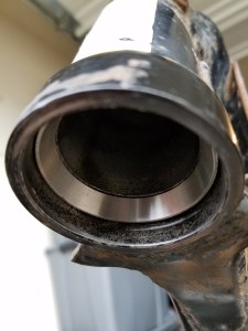
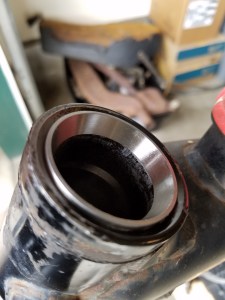
In the same setting we also have the cylinder barrel. This will be the first of many parts to see the blasters, glass media, as I have before used aircraft stripper, and while successful I will happily pay to have this done from here on out. The main reason this is pictured is prior to shipment elsewhere, for a very good reason. Also, another part return from a mistaken sending of a piston wrist pin, instead of a desired crank pin.
The reasons for shipping off the barrel are now apparent. I chose to have cylinder reinforcement take place to correct a known issue that can occur. A poor design element is that of the head stud mounting bases being cupped at their base and open, instead of throughout to the bottom of the barrel. Thus, the aluminum can in extreme scenarios of use and engine capabilities, literally split in half. So, this can be corrected, or enhanced at least, by extending bolts that start at the bottom of the jug and thread through to the head stud bases, creating a much stronger unit. There is another similar situation that occurs at the barrel base along its own mounting nuts. Since the barrel itself is also secured only at the bottom rather than through the top, here to is another area of concern. Others have managed to engineer through plugs that create mounting tension through the entire barrel, but I elected to use upgraded steel nut fasteners readily available, contrasting that of the stock aluminum ones.
Documentation, documentation, documentation. While the pictures only partially show the intricacies between the matrix of these moving parts, the difficulties in knowing overall how it will go back together comes with some factor of ease for attentive minds. Also, the use of parts diagrams and repair manuals, from both oem and aftermarket sources in electronic and printed sources allow accurate guides to follow. Generally speaking too, keep things organized and together in a fashion that makes sense to you, which takes drastically different forms for people, be it good or bad simple oddities like these make us all unique. Documentation now for you, and yes more screw head fasteners that charm and bring a smile to my face knowing they are well and gone.
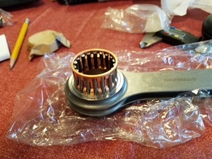
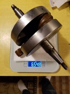
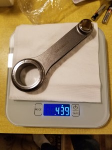
Recall my earlier mention for an obscure part number with little explanation, YA-TT5>-05571N Carrilo Rod 3.5mm? Only if you knew what that was already would I have expected as such, and if not this should be your first curiosity towards it as I will know explain. We have here a crucial device, though as is nearly any in an internal combustion engine, whose construction is a static shaft, and sole purpose is to transfer energy from the vigorous explosion altering a solution of air and fuel to heat and expansion, to source of exacting circular rotation. The force behind this rotation is of course torque, the force from fulcrum of the crank center line, acted upon the crank pin at a measurable radius, and horse power being the ability at how quickly such event occur. So, why is this one special, why should we care? This connecting rod will be one aspect of our bored and stroked motor, from 500cc (well 499, 87mm x 84mm) to nearly 570cc (566, 89mm x 91mm). If you were to ask me why go through all this trouble and expense if I really don’t have any intention of needing such a motor for any racing purpose or anything similar, would be simply that I desired to. I suppose there isn’t really a good reason or validation either way so long as in the end the machine can serve a purpose of movement, though there will be much more enjoyment and fulfillment in looking at this machine, than its previous iteration as an added benefit. The rod itself is a forged steel, H beam design, that is 3.5mm shorter than stock, thus our 7mm stroke increase. Though the rod itself does nothing to accomplish this increase, that will come upon the crankshaft later. Do note on the one measurement how much, or how little, crank webbing will be left once this is to occur. I was cautious to contact Crank Works expressing my concern on this as I was hoping to have them modify and assemble this crank. While no guarantees by picture alone, they were more than willing to take everything along with a work sheet of what I wanted and would then provide feedback. So, the pictures.
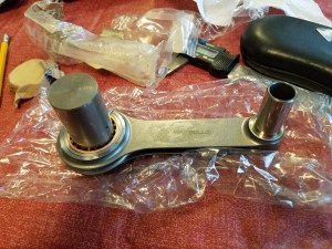
Even now, with all of the work that will have to go into this engine aspect (and I apologize on the usage of motor vs engine if I have done previously, this is an engine by definition, I’ll try not to lead you further astray from here), there are other design concerns that arise. You can’t simply alter crankshaft geometry alone and have a larger displacement without consequent effects. In this case, regards to design choice there are two main ones to determine before connecting rod selection, either have a short rod with higher rod angle and subsequent piston side thrust to cylinder wall wear, but fitting in the same engine outside dimensions, or utilize a same length connecting rod which will have a lower rod angle versus the other choice, less wear, though requiring a spacer under the cylinder barrel and effecting the outside engine dimensions. Even with these aspects, there is also the concern of how this change can affect the engines running characteristics in practice. I don’t claim to really have shareable knowledge here, you can look elsewhere, but how and when the cylinder fills and expels its gasses is changed to a degree. Thus, if you would have guessed, went the route of short rod, with the acceptance of possible faster piston and cylinder wall wear, with some possible performance gains as well. Here are just some of the notes I made concerning these ideas, along with others at the time like static compression ratios and rotating assembly masses, though they are random notes and not exacted or accurate 100%, there are various online calculators that can suffice such needs.
Coming out of theory and ideas, we go back to working with our hands, less so our minds. More dirty, gritty, oily and gummy persistence requires our attention and documentation.


Next, some measurements whose sake is mostly that of curiosity. Well, not entirely true as I would need these to compare against work to be performed, as the cranks’ mass will be altered as per more of my desires. At this point, the crank was ready to leave my care and sent to another. Admittingly, it would be quite some time until I would see this device again, but all things in due time with on open mind. The previous gallery of notes alluded to these actions, and with more individual descriptions on various rotating assembly masses, these being the only such pictured.
More parts from blasting, again a choice I will be very happy with. There is also the results of two different machining processes. First, note the valve job that occurred and the opening of the valve seat throat to match the 49mm intake valve. If you are needing to do this yourself, you can use the stock seats as there is plenty of material to work with. There is also in the head new Kibblewhite valve guides installed, and the results of engineering hopes. The intake spacer mounts as needed to the head through the existing mounts, and examine the port size increase that will need further work, nearly a 39% cross-sectional increase over the SR500 head size (34mm vs 40mm). Another issue that can be seen is the lack of a mounting tab behind the output shaft. It was broken off and would need fixing, as many tend to do, and so the Kedo weld on kit exists as a cure, with some machining providing a base to accomplish this.
A few pictures of the engine casting put together to enjoy the cleanliness that comes from the blasting process. Also, a closer look at the head stud through bolts and small oil line adapters, of which there will be boxes and bags galore.


A shift in focus now from the engine, to the holding source for the needed fuel to make it all work, the fuel tank. What previously was the first chosen item to start work on after disassembly, would now some two and a half years later deserve some of our attention. The process of removing all tarnish, rust and crud and following storage has led to a fairly clean inside. Though, in hopes of never having to tinker with it again, I’ll elect to apply a sealer to the inside. The KBS tank sealer kit to me seemed the best quality and best supported. Now, there is a great deal of care that can be taken during the process, this ended up being an 4 hour plus endeavor in hopes for optimal results, not even including curing and out gassing which will take weeks to fully finish. Also, the preliminary steps to care for the outside of the tank are apparent, and this will be essentially the last work on the tank that I will do. All body filler, priming, and painting will occur from other individuals, as I attest many times to my lack of quality painting skills. Thanks to individuals to follow, here to Shawn for pulling the dents out at his shop, a place where other friends projects reside.


A single oddity here, an isolated spring whose purpose requires part number reference for use, and although many things like these springs could have been reused, I can claim that the end result is a new bike as a consequence.

Various engine pictures for artistic reasons, as simple as it is it all just looks cool, to me at least and I’ll gamble others as well.


It’s now time to test out the fitting of the engine once again, now checking what more will need to be done to the intake spacer. As you can see, quite a lot. I knew this would occur, but was hopeful not as much with regards to the angle at which the carb is mounted. Others have overcome this by notching out the frame where there is interference and welding in a new section that clears or bends around near the top of the carb. What I decided to do instead was to angle the spacer in such a way that the carb sits as close to straight in the frame as possible. This will solve the interference issue first, and allow some ease in deciding how to route a pod filter later, albeit far too much filter for the engine size, but that will come.
A sense of loss and curiosity now pours out in this image. This will be the last such image showing the original tank paint, as altered it may be at this point. Only with the random collections of new, old, and in between from these parts can you sense the possibility of another direction the project could have gone aesthetically. This may indeed be a good thing for you the reader, for your mind can make its own decisions on where you might have gone at this stage had you such a project and curiosities in your vision. So, here it all is, or could have been one last time.

Continue below,


